Principles and Applications of Multi-Frequency 3D Ground-Penetrating Radar Technology
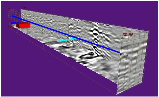
I. Technical Overview
Multi-frequency 3D Ground Penetrating Radar is an advanced geophysical exploration tool that transmits and receives high-frequency electromagnetic waves to map subsurface media distribution. Compared to traditional single-frequency radar, it employs multi-frequency antenna arrays to achieve higher resolution, greater detection depth, and more comprehensive underground data acquisition.
II. Working Principle
2.1 Electromagnetic Wave Propagation Mechanism
Ground-penetrating radar operates based on the propagation characteristics of electromagnetic waves in different media:
- Launch Phase: The antenna emits high-frequency electromagnetic pulses into the ground (typically in the range of 50 MHz to 2.0 GHz).
- Dissemination ProcessElectromagnetic waves propagate through underground media and undergo reflection, refraction, and scattering when encountering interfaces with different dielectric constants.
- Receiving: The receiving antenna captures the returned electromagnetic signals and records their amplitude, phase, and time delay.
- Data ProcessingProcess raw data using professional software to generate 2D cross-sections or 3D images of subsurface structures.
2.2 Multi-frequency Synchronization Technology
The core innovation of the multi-frequency 3D ground-penetrating radar lies in its multi-frequency synchronous operation mode:
- Multi-channel array: Equipped with an antenna array of 2 to 32 channels, each capable of operating independently at different frequencies.
- Frequency RangeThe low-frequency antenna (50-200 MHz) enables deep detection, while the high-frequency antenna (400 MHz-2.0 GHz) delivers shallow high-resolution imaging.
- Sync Collect: All frequency channels operate simultaneously to ensure data collection consistency and integrity.
- Data Fusion: Fuse data across different frequencies using algorithms to obtain a complete subsurface structure profile from shallow to deep layers.
2.3 3D Imaging Technology
3D Ground Penetrating Radar achieves volumetric imaging through the following methods:
- Grid ScanCollect data continuously along the survey line to create a dense 2D profile array.
- Spatial interpolationUse data from adjacent survey lines for spatial interpolation to construct a continuous 3D volume.
- Slice View: Slice 3D datasets from any angle to generate horizontal slices, vertical cross-sections, and isosurface plots.
- Target Detection: Intuitively visualize the spatial morphology and distribution characteristics of subsurface anomalies using 3D visualization technology.
III. Technical Advantages
3.1 offers high detection accuracy
Achieves centimeter-level positioning accuracy to precisely identify underground targets with diameters smaller than 10 cm, meeting the requirements for high-precision engineering inspections.
3.2 has a large detection depth
With a low-frequency antenna array, maximum detection depth reaches 50 meters, ideal for deep geological structure surveys and large-scale underground engineering inspections.
3.3 resolution is excellent
The high-frequency antenna delivers millimeter-level longitudinal resolution, clearly revealing thin-layer structures and minor defects such as concrete cracks and rebar distribution.
3.4 boosts work efficiency
Multi-channel synchronous acquisition significantly boosts data collection speed, capturing complete 3D data in a single scan to reduce on-site operation time.
3.5 Adaptable
Operates in diverse complex environments, including urban roads, tunnels, bridges, dams, and mining sites.
IV. Key Technical Parameters
| Parameter Item | Technical Specifications |
|---|---|
| Antenna Configuration | 2-32 Channel Multi-Frequency Array Antenna |
| Operating Frequency | 50 MHz - 2.0GHz |
| Detection Depth | 0 - 50m (depending on antenna frequency and medium) |
| Detection Accuracy | ±1 cm |
| Scan Rate | 1-10240 scans/sec (optional) |
| Resolution | ≤1 cm |
| Measurement Method | Point measurement, distance trigger measurement, continuous measurement, automatic cruise |
| Display mode | Pseudocolor, Stacked Waveforms, Grayscale, Single Channel Waveform, 3D Display |
| Location System | Supports GNSS, TPS, and measuring wheels; compatible with major GPS/RTK brands. |
| Battery Life | Built-in battery ≥8 hours |
| Operating Temperature | -30℃ ~ +70℃ |
5. Typical Application Scenarios
5.1 Engineering Geological Investigation
Detects underground geological hazards such as piping at river embankments and dam foundations, karst collapses, subsurface voids, fractured zones, ant nests, ice layer thickness, and abandoned coal mine areas to provide reliable geological data for engineering design.
Building quality inspection for 5.2
Detect structural defects such as wall cracks, voids, and rebar distribution; evaluate foundation treatment effectiveness to ensure building safety.
5.3 Underground Utility Mapping
Precisely locate underground municipal pipelines, detect civil air defense facilities, and identify obstacles in foundation engineering.
5.4 Archaeology App
Non-destructively detect the distribution of archaeological sites such as ancient tombs, city walls, and roads to provide a scientific basis for excavations and protect cultural heritage.
5.5 Public Security Criminal Investigation
Quickly locate buried evidence such as human remains, firearms, knives, and drugs to accelerate case resolution.
5.6 Road and Bridge Inspection
Investigate adverse geological bodies, detect pavement layer thickness, cracks, and subgrade defects in highways, and assess the health of bridge foundations.
5.7 tunnel detection
Inspect primary lining, support thickness, secondary lining thickness, rebar distribution, grout density and defects, and invert quality.
6. Data Processing Workflow
- Data CollectionConduct grid-based scanning using multi-frequency 3D ground-penetrating radar on-site to acquire raw radar data.
- Preprocessing: Remove noise interference and perform time-window correction, gain adjustment, and background removal.
- Speed AnalysisDetermine the propagation velocity of electromagnetic waves in a medium using known targets or borehole data.
- Offset Imaging: Apply offset migration to correct wave propagation paths and improve imaging accuracy.
- 3D ReconstructionIntegrate 2D profile data into a 3D volume for spatial interpolation and smoothing.
- Explain and analyzeIntegrate geological data and engineering experience to identify and interpret subsurface anomalies.
- Output Results: Generate technical reports including 2D cross-sections, horizontal slices, and 3D visualization models.
7. Technology Trends
With advancements in artificial intelligence, big data, and cloud computing, multi-frequency 3D ground-penetrating radar is evolving in the following directions:
- Intelligent explanationAutomatically identify subsurface anomalies using deep learning algorithms to improve interpretation efficiency and accuracy.
- Real-time processing: Develop a high-performance computing platform to enable simultaneous data collection and processing.
- Cloud Platform Integration: Build a cloud-based data storage and analytics platform to enable remote collaboration and data sharing
- Multi-Source Data FusionFused with data from other geophysical methods (e.g., seismic, resistivity) to enhance integrated interpretation capabilities.
- Miniaturized and PortableReduce device size and weight for easier field operations
VIII. Conclusion
Multi-frequency 3D ground-penetrating radar, a key tool in modern geophysical exploration, leverages its high precision, deep penetration, and high efficiency to play an increasingly vital role in engineering inspection, geological surveying, and public safety. Wuhan Shilong Technology Co., Ltd. continues to invest in R&D, constantly optimizing product performance to deliver more advanced and reliable underground detection solutions for our customers.